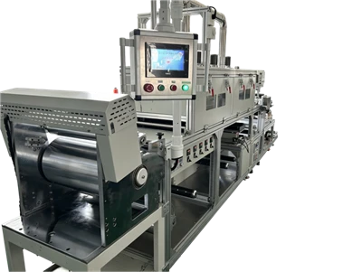

A roll comes off the line and measures even across the width. Look along the machine direction and a line or two runs from one end to the other. Tilt the web under a light and the line stands out. In English literature this goes by machine-direction streaks. Ask three people on the same line and you may get three explanations. What plants actually report usually falls into four patterns.
1. The line always sits at the same position across the width, and a fresh substrate roll does not move it.
2. Widths differ. Some look like a hair, some like a shallow groove.
3. The blade has been pulled, remounted and the pressure adjusted, and the line is still there.
4. Trials look clean, and the line turns up after several thousand metres of production.
Optical films, battery electrodes, release liners and adhesive tapes all count as high precision work. On optical film a single line scraps the whole roll. On electrodes it carries into slitting and stacking. On tapes and release liners it prints through to the next step.
So where do these streaks come from. Take the causes one at a time.
A Nick on the Blade or Die Lip Drags a Line Down the Web
One tiny nick is enough. A blade edge or a slot die lip picks up a mark, and slurry leaks past it a little more than the rest. The spot does not move. The extra slurry lays down as a line at the same position across the width, running the full length. A bigger nick makes a wider line.
These lines have a look of their own. The width holds steady, the position stays fixed, and a change of slurry does not move it. Under a light the film either side of the line reads flat. Only the line itself comes out slightly thick or slightly thin.
Where does the nick come from? A tool touched the edge during mounting. A blade scraper was dragged across it during cleaning. Dried slurry got pulled through. One cause hides better than the rest. The edge leaves the store with a fine scratch already on it, and it only shows once the blade is on the machine.
Hold a magnifier to the edge under a light and the nick is often tens of microns. Measure how far the line sits from the web edge in millimetres. Take that number to the blade and measure the same position. The direction is usually settled.
A coating machine manufacturer hands over an edge and lip inspection record at delivery. That gives the crew a baseline on acceptance day. A line saying the edge is smooth is worth nothing.
Particles and Skins in the Slurry Get Dragged Into Stripes
A particle reaches the blade and cannot get under it. Skins and agglomerates behave the same way. Slurry flows around the obstruction and leaves a line behind. These start thin and hold their position, and they widen slowly as whatever is stuck grows.
Lift the slurry out with a stirrer. Look at what clings to the wall first, then what builds on the drum floor. The soft base layer separates from the hard skin, and the hard part is the source. Slurry left on the blade during a stop dries into a skin, and the next start drags it through.
Bubbles take the same route. A bubble breaks under blade pressure and leaves a shallow line at the break, usually narrower than a particle line.
Filter mesh is sized against the largest particle in the slurry. Too coarse and the particles pass through. Too fine and the flow resistance climbs. Pass a sample through a mesh and look at what stays on the surface. The question answers itself.
Filtration method, mesh size and change-out interval are best written into the proposal. A coating line supplier who sets them out leaves the crew with a procedure to follow.
Roll Damage and Clogged Gravure Cells Leave Fixed Lines
Start with one action. Stop the line and walk a magnifier along the roll faces. A mark on the face sits at the same position across the width as the line on the web.
So which roll is printing? Coating, backing and guide rolls all pick up a mark sooner or later. A scratch, a dent or a patch of worn plating prints once per turn. These lines travel with the roll, hold their position and vary a little in spacing.
Micro-gravure has one more. Slurry dries inside the cells, those cells stop carrying anything, and a fine line appears on the web. A clogged cell does not clear itself, so cleaning has to be scheduled. Ultrasonic or chemical, depending on the plating and the cell depth.
Surface treatment, plating hardness and cell depth are worth stating in detail. A coating line manufacturer who writes them down gives the cleaning interval something to stand on.
Not Enough Levelling Time, and Fine Lines Stay on the Surface
Slurry needs a moment after it leaves the blade to level itself out. Run the line faster, raise the viscosity or thin the coating, and that moment disappears. Fine traces from the blade stay where they are and read as a set of lengthwise lines. They show up more near the edges.
These look different from a nick line. They come in groups at similar spacing and read like fine ripples under a light. Run a finger along them and there is no groove to feel. That tells you the difference is thickness only.
Let the slurry temperature drop and the viscosity rises with it. Slurry that has been sitting in the drum carries a cooler layer against the wall. Material drawn from there behaves differently from the rest.
Slot dies have a spot of their own. Uneven distribution inside the manifold leaves the lip delivering thick and thin across the width, and that arrives on the web as lengthwise bands. The lip adjusting screws and the shim edge both show up directly in what leaves the lip.
A machine builder who has worked on head design will hand over the machining tolerances for the manifold and the shim. Is the levelling window wide enough? Put a low-speed sample and a high-speed sample side by side and you have your answer in minutes.
How to Identify the Real Cause
Do not start by swapping the blade. Get the order right and the range narrows quickly.
Before the oven, run a wet film gauge across the web. A line already present in the wet film comes from the metering section, so the blade, the lip or a roll. A wet film that measures flat points somewhere else. So does a line that only appears after drying.
Then measure the position. Use a steel rule to find how far the centre of the line sits from the web edge. One number per line. Stop the line and look for the same position on the blade and on the roll faces. A nick, a scratch or a clogged cell settles the direction. A line that drifts during a run points at tension and web handling.
One step gets skipped easily. Clean the slurry path once. Fit a fresh filter mesh, circulate the slurry through it and run another short length. A line that disappears or moves came from the slurry. A line that stays exactly where it was came from the hardware.
The same roll at two speeds is a useful comparison. A line that only appears at high speed usually belongs to the levelling window. A line that sits in the same place at both speeds belongs to the hardware.
Once the direction is clear, half the work is done. For anything that does not add up, ask for the data behind it. Can an equipment supplier pull the roll and blade inspection records on the spot? One question answers that.
A coating line supplier who keeps samples from several line speeds during the trial gives you a reference for later. Whether a coating machine manufacturer keeps a process team shows up at this stage too. Some line problems cannot be read off a parameter sheet. Someone has to stand at the machine and run with it.
How to Improve Machine-Direction Streaking
Cleaning the blade once will not hold for long. The hardware and the slurry have to move together.
Make grinding and polishing the edge a fixed step, with a record handed over before shipping. Soft covers on and off the machine, so nothing gets knocked in handling. Bamboo or plastic scrapers for cleaning, never a metal tool. A weekly pass along the edge with a magnifier, and the position of any nick written down. After a few months you know which section is most exposed.
Mesh size is set by the largest particle, and the inline filter is changed on schedule. Circulate the slurry to vent it before a run. During a long stop, drain slurry out of the blade and the line so it never dries in place.
Plating hardness, cell depth and cleaning interval all belong in the proposal. Ultrasonic cleaning for clogged cells, and no aggressive chemistry on thin plating. Backing roll runout and face condition get a periodic recheck.
Time for levelling is the last piece. Leave enough of it. Hold slurry viscosity and temperature inside the working range, and set the gap and the line speed together. Where it is needed, leave a levelling distance after the head. A small addition of levelling agent takes out a group of fine lines on low-surface-tension slurry.
It is also why an OEM insists on a trial with your slurry before quoting. A quote with nothing but a price on it usually has nothing behind it. A manufacturer who writes cleaning and change-out intervals into the operating manual leaves the crew with something to follow. An equipment supplier should leave roller face, blade edge and gravure cell rows in the acceptance sheet. That saves time on the day.
Conclusion
Streaks after coating are seldom caused by one thing. A nick on the blade, particles and skins in the slurry, roll damage and a narrow levelling window. They tend to stack up together. On the same line, two of them often arrive at once.
Stable production needs material analysis, process testing and equipment design to line up. Defects like this are judged far more strictly on optical film and electrodes, where one line becomes a whole roll of scrap. Holding the same level two and three years in is what counts.
In the end it comes down to edge condition, slurry cleanliness and the levelling window, and how the three are set together. Whether a coating machine manufacturer can put numbers on all three becomes clear in a few minutes of conversation. Fixed-position defects like this come up often in custom work. Innater has built coating machines to order across a range of products and processes. Precision, thickness and uniformity are worked out against your slurry and your target thickness.
The roll and edge records left at delivery exist for exactly this. A coating line manufacturer who hands them over gives you a comparison for every blade change and every cleaning. A coating line supplier who prices filtration, cleaning and consumables into the configuration gives you a complete figure.
In the technical agreement, a manufacturer usually sets out the acceptance basis for streaks as a separate line. How many points and at what speed, so both sides read the same scale. An OEM also writes down who handles cleaning and part replacement. That clause only earns its keep in the second year.
The first three months after the line arrives test people more than the day the contract is signed. Whether a machine builder stays with you to production is usually clear by then. Samples a supplier leaves behind at commissioning become the reference when something goes wrong.

resist coating - Innater

industrial rivet machine - Innater
Published by Innater Intelligent Equipment Co., Ltd, a maker of non-standard coating machines and automated lines. Email 13316631159@163.com | Website https://www.getinnater.com/ | Tel +8613316631159