
A roll comes off the line and the film shows round marks. Some stand proud, some have burst and left a crater edge. Tilt the web under a light and they stand out. Ask three people on the same line and you may get three explanations. Nobody agrees on whether it is the slurry or the machine.
1. The marks land at random and differ in size. This roll has them, the next one has them too.
2. Change the stirrer speed and they ease off for a day or two, then come back.
3. Drop the viscosity and the bubbles burst, but now the film shows pinholes.
4. Trials run clean, and the first production shift brings them out.
Optical films, battery electrodes, release liners and label stock all count as high precision work. One mark in a visible area scraps the whole roll. On electrodes it weakens adhesion. On optical film it fails a full inspection. Defects like this cannot be picked out later, so the batch gets downgraded.
So where do they come from. Take it section by section.
Where the Air in the Slurry Comes From
Mixing puts air in. Raise the impeller speed and the surface pulls into a funnel, and air goes down with it. A circulation return line aimed at the surface does the same thing.
Why does that air not rise back out? Run the numbers. By Stokes law, a 50 micron bubble in a 500 mPa·s slurry climbs at under 3 microns per second. A 100 micron wet film needs half a minute for that bubble to reach the surface. Ahead of the oven, the film may only have a few seconds.
Higher viscosity slows the climb further. A thin slurry sheds most of its air in an hour. A high-solids slurry still holds it a day later. Raise the surface tension and the bubble skin gets stronger, so it takes longer to break.
Pull a sample on a glass rod and drop it on a glass plate. Watch whether the bubbles break on their own. The ones still standing after ten minutes tell you the degassing step was too short. Drum level matters too. Below the impeller, the blades stir air straight into the batch.
Defoamer is a separate question. Too little and the foam holds. Too much and you buy pinholes and orange peel instead. Most slurries have one narrow band, and a trial is the only way to find it.
One scene repeats. The morning batch coats clean. The afternoon batch on the same machine does not. Only one thing changed in between. Mixing stopped for two hours with nobody watching, and the level dropped below the blades. Ask how long the batch stood before the trial, and the two batches usually line up. A coating machine manufacturer that asks this first has probably been caught out by a high-solids slurry before.
Why the Suction Side Leaks Air You Cannot See
The run from the drum to the pump inlet sits under negative pressure. Any quick coupling, clamp or seal not fully tight lets air in. A liquid leak you can see. Can you see an air leak? No, and that is why this one gets skipped.
A diaphragm pump adds cavitation on top of that. Local pressure in the chamber drops below the vapour pressure of the solvent, bubbles form, and they collapse again at the outlet. Ethyl acetate boils at 77 °C at atmospheric pressure. Under suction in the pump chamber, it boils at room temperature. These bubbles are far too fine to see in the slurry. They show up on the web.
There is a crude way to find the leak. Circulate the slurry and brush soapy water on every coupling and clamp. The one that foams is the one drawing air. A line carries a dozen joints, and the walk takes under ten minutes.
Filters are the next suspect. Once the mesh loads up, pressure downstream drops, dissolved air comes out of solution and arrives as a string of fine bubbles. Set the change-out interval too long and this shows up on schedule.
Dead legs and long horizontal runs collect air. With no venting at start-up, the trapped pocket gets pushed along in slugs, which lands as bubbles at intervals on the web.
Pipe route, pump type and vent points belong on the drawing. Put them there and the crew knows where to vent at start-up. An equipment supplier who fills that page in properly saves a lot of walking later.
Air Folded In Ahead of the Blade
The wet film picks up a layer of air as it leaves the blade. Raise the level ahead of the blade, open the gap or push the speed, and air goes in with it. Squeezed between rolls, that air has nowhere to go and ends up pressed into the film.
Micro-gravure and anilox rolls are worse at speed. The roll lifts a film of slurry out of the pan, and cells take in air along with the slurry. The transfer lands as bubbles on the web.
Slot dies have their own version. Air left in the manifold gets pushed into the coating during the first minutes of a run. With no venting, or no venting sequence after a stop, the first few hundred metres carry a regular pattern of bubbles.
Watch the slurry ahead of the blade. A quiet surface is normal. Once it rolls, or a layer of fine white foam sits on top, air entrainment has already started.
The head is closed up once it is built, so none of this is visible from outside. The margin a machine builder leaves in the collection chamber and the vent points only shows up once the line runs.
The Substrate Breathes, and a Fast Ramp Seals It In
Porous substrates hold air of their own. Nonwovens, paper and coated paper carry air in their pores. When the slurry goes down, that air pushes up and forms a bubble. Thicker substrate and more open pores make it worse.
A fast ramp traps what should have escaped. The surface skins over first, solvent and air cannot get out, heat expands them, and the skin lifts. Once cured, that is a blister. Hold the first zone at 60 to 70 °C and run slower through it, and the bubbles have time to leave. Start hot instead and no later zone will undo it.
Thick coatings behave the same way. A bubble has to travel from the bottom of the coating to the surface, and doubling the thickness doubles the distance. A high-solids slurry is more viscous, so the climb is slower still.
Hold an uncoated roll of substrate against a light. The open areas read brighter. Change the substrate batch and the bubble count changes with it.
Oil and dust on the substrate form a spot the slurry will not wet. The slurry flows around it and dries into a crater. It looks like a bubble, comes from somewhere else, and takes a different route to find.
The ramp follows the slurry and the coating thickness, and that belongs in the oven discussion. A coating line manufacturer who writes the temperature and the air speed for each zone into the proposal saves a commissioning week.
Telling the Sources Apart
Do not start by adding defoamer. Get the order right and the direction clears up quickly.
Before the oven, look at the wet film under a magnifier. Bubbles already there come from the slurry, the feed line or the head. A wet film that reads flat, with blisters only after the oven, points at the substrate and the ramp.
Then run a standing test on a wet sample. Draw it down on a glass plate and leave it ten minutes. Bubbles that disperse or shrink come from mechanical entrainment, and degassing will handle them. Bubbles that stand still point at surfactants or a reaction in the formulation.
Swapping in a different substrate roll is an easy comparison. Fewer bubbles, or a different pattern, puts it on the substrate. The same count in the same places sends you back to the slurry and the machine.
Pump speed is worth a try as well. Drop the circulation pump one step. If the bubbles fall away, the suction side is the source. The test costs a few minutes.
How the marks are spread says something too. Even coverage across the web points at the slurry. Clusters every few metres point at trapped air in the pipework. A pattern that moves with a new roll points at the substrate.
Once the direction is clear, half the work is done. For anything that does not add up, ask for the data behind it. Can the pump type and the vent layout be pulled up on the spot? One question answers that. Some bubble problems cannot be read off a parameter sheet. Someone has to stand at the machine and watch the slurry run, and a coating machine manufacturer who keeps that person on staff shows it here. An equipment supplier and a coating line supplier will both say they can do it. The difference only appears on site.
Keep samples from several line speeds during the trial, and you have a reference for later. Whoever does this saves themselves trouble down the line. A coating line manufacturer only has to add one line to the trial sheet.
What Actually Reduces Them
Defoamer in the drum is the last line, not the first. Leave the earlier sections alone and it will not hold for long.
Standing time has to be built in. Let the batch rest before it goes to the machine, and keep the drum level above the impeller. Keep the return line off the surface. For high-solids slurries, vacuum degassing beats standing. Pull the vacuum below -0.08 MPa and half an hour does what half a day of standing would.
Sealing and venting carry the feed section. Recheck the couplings on the suction side on a schedule. Pick the pump against the slurry viscosity, and add damping or a buffer tank where the pulsation is heavy. Vent in sequence at start-up and leave no dead legs.
Level and gap belong together. Set speed and gap as a pair, and do not trade process window for throughput. Vent points in the manifold go back in place after every cleaning, and that belongs on the fitting checklist.
On the substrate and drying side, remove dust and static, and control moisture. A porous substrate can take a thin low-solids pre-wet first. Keep the first oven zone low and run slower through it, so the bubbles have time to leave.
It is also why an OEM insists on a trial with your slurry before quoting. A manufacturer who sends nothing but a price usually has nothing behind it. Degassing and change-out intervals belong in the operating manual. A manufacturer who writes that page leaves the crew with something to follow and fewer phone calls to make.
Conclusion
Bubbles on the coating surface are seldom caused by one thing. Air carried in the slurry, air drawn in through the feed line, air folded in at the head, plus substrate outgassing and the ramp. They tend to stack up. Does the old recipe still hold when the formulation changes? Rarely, and the whole set goes back on the table.
Stable production needs material analysis, process testing and equipment design to line up. A bubble looks like a small thing until it lands on optical film or an electrode and the batch is downgraded. Holding the same level two and three years in is what counts.
In the end it comes down to degassing, sealing and the oven ramp, and how the three are set together. Whether a coating machine manufacturer can put numbers on all three becomes clear in a few minutes of conversation. Problems like this come up often in custom work. Innater has built coating machines to order across a range of products and processes. Precision, thickness and uniformity are worked out against your slurry and your target thickness.
Write the acceptance basis for bubbles into the technical agreement as a separate line. How large counts as a defect, and where the sample is taken, so both sides read the same scale. A coating line manufacturer and a coating line supplier who are detailed on those lines leave less to argue about later. A machine builder who has worked on manifold venting takes a batch of start-up bubbles out of the picture. An OEM also writes down who supplies the defoamer and the filter consumables, and that clause only earns its keep in the second year.
The first three months after the line arrives test people more than the day the contract is signed. Whether a supplier stays with you to production is usually clear by then.
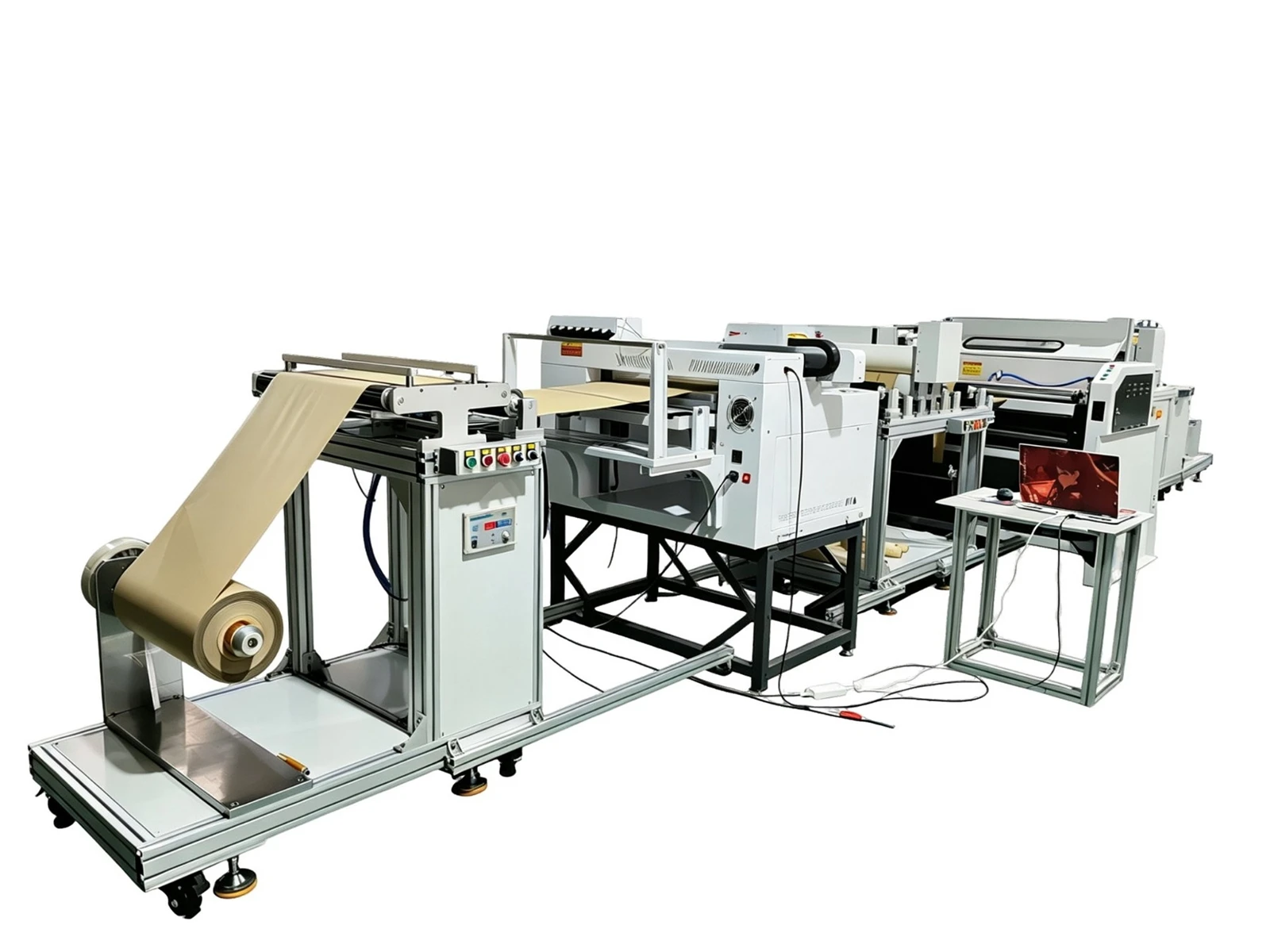
release liner production line-Innate

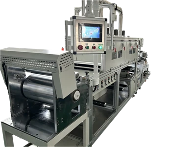
semiconductor coater-Innate
Published by Innater Intelligent Equipment Co., Ltd, a maker of non-standard coating machines and automated lines. Email 13316631159@163.com | Website https://www.getinnater.com/ | Tel +8613316631159